Turbine Monitor User Guide
1. Wi-Fi Connection
2. Access Dashboard
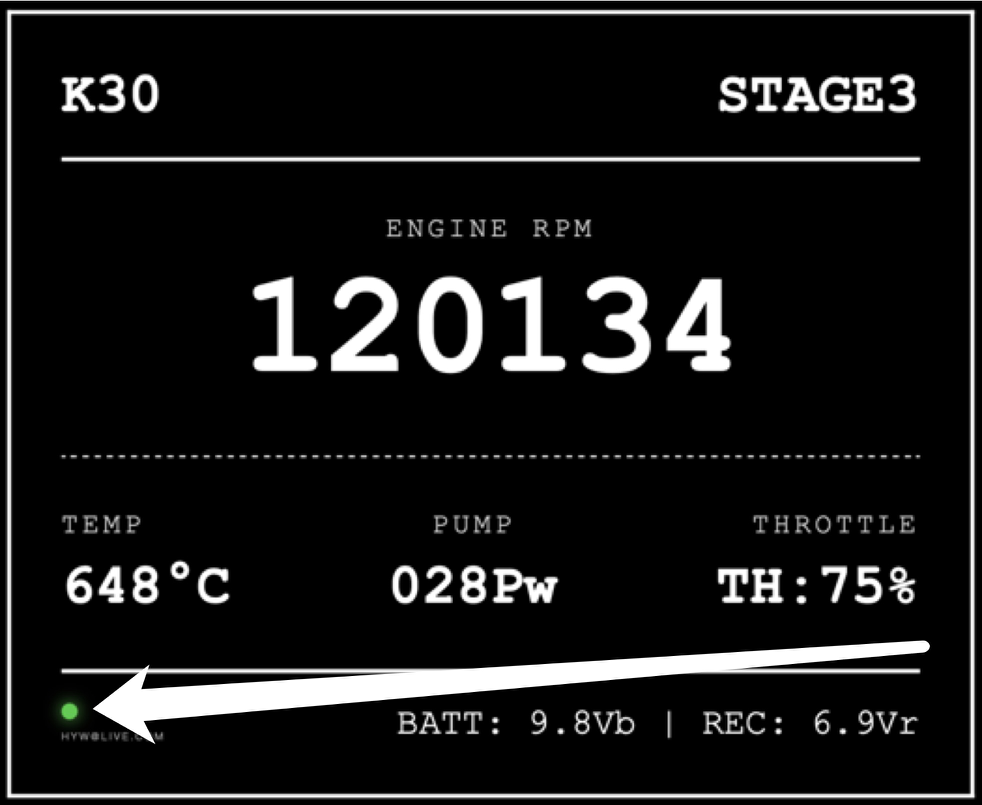
3. Status Indicator (Bottom Left of Figure 1)
Figure 1
4. Resources & Updates
Turbine Monitor technical reference manual
1. Serial Configuration
2. Packet Structure
All packets follow a fixed frame format:
3. Payload Memory Map
(Offsets are zero-indexed, starting from the first header byte 0xFC)
Offset (Index) | Length | Data Field | Data Type & Description |
14 ~ 15 | 2 Bytes | RPM | 16-bit Unsigned Integer, Little-Endian. (Note: Multiply the raw value by 100 to get actual RPM) |
22 ~ 24 | 3 Bytes | Model | ASCII String (e.g., K30) |
30 ~ 37 | 8 Bytes | Status | ASCII String (e.g., Stage3, Running) |
46 ~ 52 | 7 Bytes | Throttle | ASCII String (e.g., Th:Idle) |
54 ~ 59 | 6 Bytes | VB | ASCII String (e.g., 9.4Vb) |
62 ~ 66 | 5 Bytes | VR | ASCII String (e.g., 6.9Vr) |
70 ~ 74 | 5 Bytes | Pump Power | ASCII String (e.g., 036Pw) |
78 ~ 82 | 5 Bytes | EGT | ASCII String (e.g., 347°C) |
(Note: Offsets 22-82 are only available in 0x52 Long Packets. Short Packets only contain the RPM data.)
Example Data Payload
1. Raw Hex Data Dump
FC C5 52 00 00 40 00 00 24 00 14 00 5B 01 CA 00 02 00 00 00 00 00 4B 33 30 20 20 20 20 20 53 74 61 67 65 33 20 20 00 00 00 00 00 00 00 00 54 68 3A 49 64 6C 65 00 20 39 2E 33 56 62 00 00 20 36 2E 39 56 72 00 00 30 33 36 50 77 00 00 00 33 34 37 B0 43 00 00 00 03 0E 5A
FC C5 0C 00 00 40 00 00 25 00 14 00 60 01 CC 00 B2 01 5A
2. Parsing Example (Long Packet - 0x52)
Taking the first line (85 Bytes) and applying the memory map:
3. Parsing Example (Short Packet - 0x0C)
Taking the second line (19 Bytes):